Selecting a flexible hose for high-pressure fluids requires more than checking a pressure number. Can flexible hoses handle high-pressure fluids? Yes, but only when the hose, fittings, fluid, and operating conditions match precisely. A hose may look strong on a workbench and still fail after repeated pressure pulses, heat exposure, or sharp bending.
In practical applications, start with the fluid type, working pressure, surge pressure, temperature range, and required flow rate. A hydraulic hose rated for oil may not suit water, steam, or aggressive chemicals. Check the manufacturer’s working pressure, burst pressure, impulse rating, and minimum bend radius. Never treat burst pressure as a safe operating limit. That mistake is common.
Connections matter equally. Poorly crimped fittings can leak beside an otherwise suitable hose. Inspect the cover for cuts, abrasion, swelling, and exposed reinforcement. Secure the assembly away from hot surfaces and moving machinery. Allow enough length for movement, but avoid unnecessary loops. Small details matter.
Test carefully.
Reliable selection also involves qualified technical advice and traceable product documentation. Engineers and experienced technicians can compare hose construction, reinforcement layers, end connections, and inspection intervals. However, even professional recommendations need review when conditions change. Pressure spikes are often underestimated. A better decision considers the entire hose assembly, not only the tube. This guide explains those choices clearly, while acknowledging one uncomfortable truth: field conditions are rarely as predictable as specifications suggest.
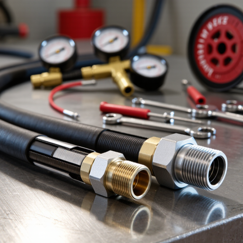
Choosing flexible hoses for high-pressure fluids starts with a clear operating envelope. Record the maximum working pressure, pressure spikes, vacuum conditions, and pump pulsations. Static pressure alone can mislead you. A hose may survive normal operation but fail during startup or valve closure. Select a working-pressure rating above every expected condition, including temporary surges.
Measure it.
Temperature needs equal attention. List the fluid temperature, surrounding temperature, cleaning cycles, and possible heat from nearby equipment. Some hose materials soften, harden, or lose flexibility outside their rated range. Confirm fluid compatibility with the tube, cover, reinforcement, and seals. Small chemical changes can matter. Do not rely on appearance.
Flow requirements also shape the correct hose size. Calculate the internal diameter from the required flow rate, fluid viscosity, density, and acceptable pressure loss. An undersized hose can create turbulence, heat, noise, and unnecessary pump load. An oversized hose may cost more and reduce flexibility. Fit the bore carefully. For moving equipment, check the minimum bend radius, impulse rating, fitting orientation, and support points. Avoid twisting the hose during installation. A field inspection should include abrasion, bulges, leaks, and loose fittings. Pressure testing must follow a controlled procedure with suitable protective barriers. My assumptions may still be incomplete, especially when flow changes seasonally. Recheck them against measured data before final selection.
| Selection Dimension | What to Define | Practical Data or Starting Range | Example Design Input | Hose Selection Implication |
|---|---|---|---|---|
| 1. Pressure Requirements | ||||
| Maximum working pressure | The highest steady pressure the hose assembly will experience during normal operation. | Specify in bar or psi. The assembly working-pressure rating must be equal to or greater than the maximum operating pressure. | 210 bar maximum operating pressure | Choose a hose assembly rated for at least 210 bar at the actual operating temperature and hose size. |
| Pressure surge and pulsation | Short-duration pressure spikes caused by pumps, valves, cylinders, water hammer, or rapid starts and stops. | Measure or estimate the peak transient pressure; do not size only from the average gauge reading. | 210 bar steady pressure with a measured 35 bar surge | The assembly must tolerate at least 245 bar peak pressure, subject to the applicable hose standard and manufacturer data. |
| Burst pressure | The laboratory pressure at which a hose assembly ruptures during a controlled test. | Burst pressure is not an allowable operating pressure. Many hydraulic hose standards specify a minimum burst-to-working-pressure ratio, commonly 4:1, but the applicable standard must be verified. | 210 bar working pressure and 840 bar minimum burst pressure where a 4:1 ratio applies | Use the published working-pressure rating, not the burst value, for design decisions. |
| Pressure drop | Loss of pressure caused by hose length, internal diameter, fittings, bends, and flow rate. | Calculate pressure drop using the actual hose bore, length, fluid viscosity, fittings, and operating temperature. | 15 m hose assembly carrying 20 L/min | If pressure drop is excessive, increase the hose inside diameter rather than increasing pressure alone. |
| 2. Temperature Requirements | ||||
| Fluid temperature | Normal, minimum, maximum, and short-term peak temperature of the transported fluid. | Record the full temperature range in °C or °F. Hose pressure ratings can be reduced at elevated temperatures. | Hydraulic oil: 20 to 100 °C, with a 110 °C short-term peak | Select an inner-tube and cover material rated for the fluid and the highest temperature. Confirm any temperature-related pressure derating. |
| Ambient temperature | Temperature around the hose, including radiant heat from furnaces, engines, exhausts, or hot piping. | Define the minimum and maximum ambient temperature separately from fluid temperature. | Ambient temperature: −20 to 60 °C | Use a cover suitable for the external environment and protect the hose from direct heat sources. |
| Temperature screening by tube material | Initial compatibility check for common flexible-hose tube materials. |
NBR: commonly used for petroleum-based hydraulic oils, typically about −40 to 100 °C. EPDM: commonly used for hot water, steam, and water-glycol fluids, typically about −40 to 150 °C depending on construction. PTFE: broad chemical compatibility and commonly used for high-temperature service, often about −60 to 260 °C depending on assembly design. |
Water-glycol fluid at 120 °C | EPDM or another specifically compatible tube may be more suitable than NBR. Always verify the exact fluid, concentration, pressure, and temperature combination. |
| Thermal cycling | Repeated changes between hot and cold conditions. | Define the number and frequency of temperature cycles, including start-up and shutdown conditions. | From 20 °C to 100 °C, 10 cycles per day | Choose a construction that tolerates repeated expansion, contraction, and pressure cycling; inspect for cover cracking and leakage. |
| 3. Flow and Hose Size Requirements | ||||
| Required flow rate | Normal, minimum, and maximum volumetric flow rate. | Specify L/min, m³/h, or US gal/min. Size the hose for the maximum required flow, not the average flow. | 20 L/min maximum flow | Use the maximum flow with an acceptable velocity and pressure-drop limit to determine the minimum inside diameter. |
| Flow velocity target | Fluid velocity inside the hose. |
Hydraulic pressure lines: approximately 3–5 m/s as a common starting range. Hydraulic return lines: approximately 2–3 m/s. Hydraulic suction lines: approximately 0.5–1.2 m/s to reduce cavitation risk. |
Pressure line designed at 4 m/s | Lower velocity generally reduces pressure drop, heat generation, noise, and flow turbulence, but may require a larger and less flexible hose. |
| Inside-diameter calculation | Minimum theoretical hose bore based on flow and target velocity. | d = √[4Q ÷ (πv)] | Q = 20 L/min = 0.000333 m³/s; v = 4 m/s; calculated minimum bore ≈ 10.3 mm | Select the next suitable nominal size with an actual inside diameter at or above 10.3 mm, then verify pressure drop and fitting bore. |
| Common nominal hose sizes | Initial size comparison based on nominal inside diameter. |
1/4 in: approximately 6.4 mm 3/8 in: approximately 9.5 mm 1/2 in: approximately 12.7 mm 3/4 in: approximately 19.1 mm 1 in: approximately 25.4 mm |
Required calculated bore: 10.3 mm | A nominal 1/2 in hose is a likely starting point because its nominal bore is larger than the calculated minimum. Confirm the actual bore from the hose specification. |
| 4. Fluid Compatibility and Installation Conditions | ||||
| Fluid type and concentration | Fluid name, chemical composition, additives, concentration, and cleanliness requirements. |
Petroleum-based hydraulic oil: commonly compatible with NBR or equivalent oil-resistant tubes. Water-glycol: commonly compatible with EPDM or specifically approved materials. Compressed air: use an air-rated assembly and consider oil, moisture, and static discharge requirements. |
35% water-glycol solution | Confirm compatibility of the tube, reinforcement, cover, fittings, seals, and cleaning agents with the exact fluid formulation. |
| Bend radius | Smallest allowable bending radius measured to the inside of the bend. | Use the published minimum bend radius for the selected hose. Avoid bending directly behind fittings. | Available installation radius: 180 mm | The hose's specified minimum bend radius must be 180 mm or less under the operating conditions. |
| Motion and flexing | Static, occasional movement, continuous motion, vibration, or torsional movement. | Define stroke length, cycle rate, travel path, and minimum bend radius during motion. | 500 mm stroke at 20 cycles per minute | Use a hose designed for dynamic service, provide adequate slack, and prevent twisting. Do not use the hose as a structural support. |
| External environment | Abrasion, ultraviolet exposure, ozone, chemicals, flame, salt spray, and mechanical impact. | Specify the dominant hazards and required protective measures. | Outdoor installation with abrasion from nearby steelwork | Use a suitable abrasion-resistant cover or protective sleeve and secure the hose away from sharp edges. |
| Electrical properties | Whether electrical conductivity, electrical insulation, or static dissipation is required. | Requirements depend on the fluid, equipment, hazardous-area classification, and applicable safety standard. | Compressed air hose near electrically sensitive equipment | Verify electrical resistance requirements and grounding practices; do not assume a hose is conductive or insulating without test data. |
| Assembly verification | Hose, fittings, crimp dimensions, cleanliness, routing, and test documentation. | The complete hose assembly must be rated for the intended pressure, temperature, fluid, and motion. Hose and fitting components should be assembled according to the applicable manufacturer and industry standard instructions. | High-pressure hydraulic assembly for industrial equipment | Inspect for correct routing, adequate clearance, no twisting, proper clamps, and leakage testing before commissioning. |
Measure normal pressure, startup surges, and sudden spikes separately. Choose a working pressure rating above the highest expected load. Burst pressure is not a safe operating target. This distinction is easy to miss.
Hot fluid can reduce pressure capacity and speed up tube aging. Check the hose temperature range against the real operating temperature. A cool test may hide problems during production.
A bore that is too small increases fluid speed, heat, and pressure loss. A bore that is too large can reduce control and add weight. Compare flow rate, connection size, and acceptable pressure drop.
Measure the complete route while the machine moves through its operating range. Keep the hose within its minimum bend radius. Avoid twisting or forcing fittings sideways. Sharp edges are dangerous.
Consider movement frequency, vibration, and cycle length. A maintenance hose may need less flexibility than one moving thousands of times daily. Check tested impulse performance and compatible end fittings.
Use bright lighting to examine the cover, fittings, threads, and sealing surfaces. Reject cuts, crushed areas, exposed reinforcement, or hardened material. Small cracks matter.
Confirm the length without stretching it between connection points. Add suitable supports and allow natural movement. Do not twist the hose while tightening fittings. Use calibrated tools and specified torque.
Inspect abrasion, blistering, corrosion, loose clamps, and fluid stains regularly. Check hidden areas behind guards or machinery. Replace hoses after severe pressure spikes, even without visible damage. Rushed inspections miss defects.
Choosing a flexible hose for high-pressure fluids begins with defining the operating pressure, temperature range, flow rate, and working environment. Can flexible hoses handle high-pressure fluids? Yes, when they are properly rated and selected for the application. The hose material must be compatible with the fluid to prevent swelling, cracking, corrosion, or contamination. Consider the required pressure rating, internal diameter, bend radius, and flexibility to ensure reliable flow without excessive stress.
A safe assembly also depends on suitable reinforcement, fittings, and connection methods. Reinforced layers should withstand pressure surges and repeated movement, while fittings must match the hose and equipment securely. Before use, inspect the hose for wear, damage, leaks, and incorrect installation. Avoid twisting, sharp bends, and excessive stretching, and support the hose where necessary. Regular inspections, pressure checks, and timely replacement can improve service life, reduce failure risks, and maintain dependable performance in demanding fluid-handling systems.

 Autowellix Autoparts